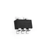
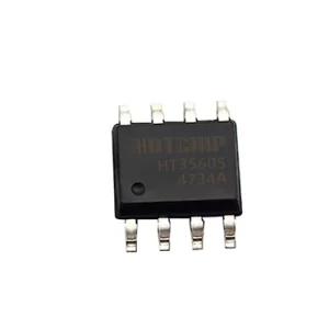
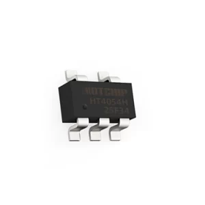
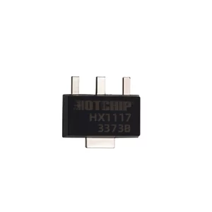
HT4056H features constant current/constant voltage linear control and requires minimal external components, making it ideal for portable applications. It operates with both USB and adapter power sources.
Utilizing an internal PMOSFET structure and anti-backflow protection, HT4056H eliminates the need for external detection resistors and isolation diodes. Thermal feedback automatically adjusts the charging current to limit chip temperature under high power or high ambient conditions, with a fixed charging voltage of 4.2V and an adjustable charging current via the PROG pin, up to 1.0A.
When the input voltage is removed, HT4056H enters a low current state, keeping battery leakage below 2μA. Additional features include a charging current monitor, input over-voltage protection, under-voltage lockout, automatic recharge, and status pins for charging completion and input voltage detection.
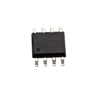
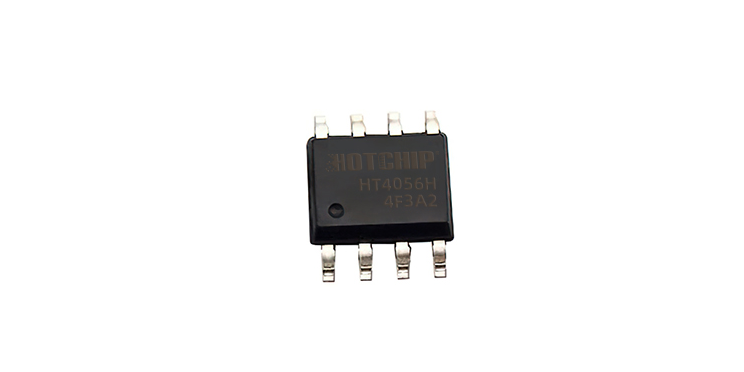
HT4056H is packaged in an environmentally friendly ESOP8 with a minimum of six external components, effectively reducing PCB layout space. It operates within a temperature range of -40°C to +85°C.
1. Specifications
(VCC=5V,VBAT = 3.6V,TJ = 25℃, unless otherwise specified)
| Parameter | Symbol | Condition | Min. | Typ. | Max. | Unit |
| Input Power Voltage | VCC | 4.5 | 5 | 36 | V | |
| Static Current | IQ | Charging Mode, RPROG=1.2k | 260 | 360 | μA | |
| Standby Mode (Charge Terminated) | 180 | 300 | ||||
| Shutdown Mode (RPROG not connected, VCC < VBAT, or VCC < VUV) | 180 | 300 | ||||
| OVP Protection Status( VCC =30V) | 180 | 300 | ||||
| Adjustable Output (Float Charge) Voltage | VFLOAT | 0°C≤TA≤85°C, RPROG=1.2k | 4.158 | 4.2 | 4.242 | V |
| BAT Pin Current | IBAT | RPROG = 1.2k, Current Mode | 880 | 1000 | 1120 | mA |
| Standby Mode, VBAT = 4.2V | 0 | -2.5 | -6 | μA | ||
| Shutdown Mode (RPROG not connected and) | ±1 | ±2 | ||||
| Sleep Mode, VCC = 0V | -1 | -2 | ||||
| Trickle Charging Current | ITRIKL | VBAT<VTRIKL, RPROG= 1.2K | 110 | 120 | 130 | mA |
| Trickle Charging Threshold Voltage | VTRIKL | RPROG = 1.2k, VBAT rise | 2.8 | 2.9 | 3 | V |
| Trickle Charging Hysteresis Voltage | VTRHYS | RPROG = 1.2k | 120 | 160 | 200 | mV |
| VCC Under-voltage Lockout Threshold | VUV | From VCC Low to High | 3.5 | 3.7 | 3.9 | V |
| VCC Under-voltage Lockout Hysteresis | VUVHYS | 100 | 200 | 300 | mV | |
| VCC-VBAT Threshold Voltage | VASD | From VCC Low to High | 100 | 125 | 150 | mV |
| From VCC High to Low | 30 | 65 | 100 | |||
| C/10 Terminated Current Threshold | ITERM | RPROG = 1.2k | 110 | 120 | 130 | mA |
| PROG Pin Voltage | VPROG | RPROG = 1.2k, Current Mode | 0.9 | 1 | 1.1 | V |
| CHRG Pin Output Low Voltage | VCHRG | ICHRG = 5mA | 0.3 | 0.6 | V | |
| STDBY Pin Output Low Voltage | VCHRG | ISTDBY = 5mA | 0.3 | 0.6 | V | |
| Recharge Battery Threshold Voltage | ∆VRECHRG | VFLOAT – VRECHRG | 100 | 150 | 200 | mV |
| Junction Temperature in Limited Temperature Mode | TLIM | 145 | ℃ | |||
| Power FET On-resistance | RON | 300 | mΩ | |||
| Soft Start Time | tSS | IBAT = 0 to IBAT =1000V/RPROG | 20 | μs | ||
| Recharge Comparator Filter Time | tRECHARGE | From VBAT High to Low | 0.8 | 1.8 | 4 | ms |
| Terminate Comparator Filter Time | tTERM | IBAT Down to ICHG/10 | 0.8 | 1.8 | 4 | ms |
| PROG Pin Pull-up Current | IPROG | 1 | μA | |||
| TEMP High-side Protection Voltage | VTEMP-H | 80 | 82 | %VCC | ||
| TEMP Low-side Protection Voltage | VTEMP-L | 43 | 45 | %VCC |
2. Product Features
- Maximum input voltage of 40V with 6.0V overvoltage protection.
- 4.2V preset charge termination voltage with 1% accuracy.
- Battery reverse polarity protection.
- BAT-VDD anti-backflow capability.
- Standby current < 2μA.
- Power consumption of 55μA in shutdown mode.
- Supports charging of 0V batteries.
- Maximum linear charging current of 2A with three-stage charging (trickle/constant current/constant voltage).
- External adjustment of charging current.
- Intelligent thermal regulation of charging current.
- Soft-start to limit inrush current.
- Automatic recharge.
- Charging status indication.
- ESOP8 green package.
3. Typical Application Circuit Diagram
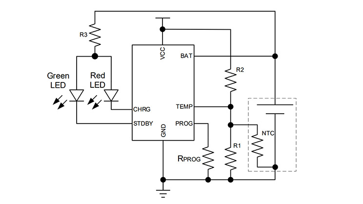 4. Pin Diagram and Functional Description
| Pin Number | Pin Name | Functional Description |
| 1 | TEMP | Battery temperature sensing pin |
| 2 | PROG | Charging current adjustment pin, with an external resistor to GND to regulate charging current |
| 3 | GND | Ground |
| 4 | VCC | Power Input pin |
| 5 | BAT | Battery Input pin |
| 6 | STDBY | Open-drain output for charging completion indication |
| 7 | CHRG | Open-drain output for charging status indication |
| 8 | NC | Not connected |
| Exposed Thermal PAD | GND | Ground |
5. Features
- Normal Charging Cycle.
- Charging Current Setting.
- Termination of Charging.
- Charging Status Indicator.
- Thermal Limiting.
- Under-Voltage Lockout (UVLO).
- Automatic Recharging.
- Stability Considerations.
- Power Consumption Considerations.
