

HT4054H is suitable for operation with USB power sources and adapter power. With its internal PMOSFET structure and built-in reverse discharge protection, it eliminates the need for external sensing resistors and isolation diodes. Thermal feedback regulates the charging current to limit the chip’s temperature during high-power operation or elevated ambient temperatures. The charging voltage is fixed at 4.2V, while the charging current can be externally set using a resistor. Once the charging current drops to a preset value of 1/10 after reaching the final float voltage, the HT4054H will automatically terminate the charging cycle.
When the input voltage (AC adapter or USB power) is removed, the HT4054H automatically enters a low-current state, reducing battery leakage current to below 2μA. The HT4054H can also be put into shutdown mode, which further reduces the supply current to 55μA. Other features include a charging current monitor, undervoltage lockout, automatic recharging, and a status pin to indicate charging completion and input voltage presence.
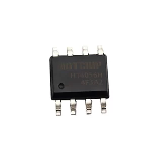
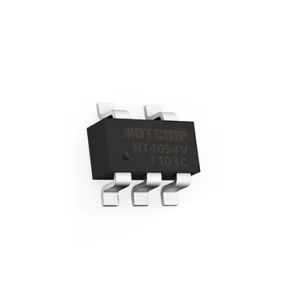
The HT4054H comes in an environmentally friendly SOT23-5 package with a minimal number of three external components, effectively reducing PCB layout space. It operates in a temperature range of -40°C to +85°C.
1. Specifications
(VCC=5V,VBAT = 3.6V,TJ = 25℃, unless otherwise specified)
| Parameter | Symbol | Condition | Min. | Typ. | Max. | Unit |
| Input Power Voltage | VCC | 4.5 | 5 | 36 | V | |
| Static Current | IQ | Charging Mode, RPROG=10k | 240 | 360 | μA | |
| Standby Mode (Charge Terminated) | 220 | 300 | ||||
| Shutdown Mode (RPROG not connected, VCC < VBAT, or VCC < VUV) | 220 | 300 | ||||
| OVP Protection Status(VCC=30V) | 120 | 250 | ||||
| Adjustable Output (Float Charge) Voltage | VFLOAT | 0°C≤TA≤85°C, RPROG = 2k | 4.158 | 4.2 | 4.242 | V |
| BAT Pin Current | IBAT | RPROG = 10k, Current Mode | 100 | 120 | 140 | mA |
| RPROG = 2.4k, Current Mode | 450 | 500 | 550 | |||
| RPROG = 2k, Current Mode | 440 | 600 | 660 | |||
| Standby Mode, VBAT = 4.2V | 0 | -2.5 | -6 | μA | ||
| Shutdown Mode (RPROG not connected and) | ±1 | ±2 | ||||
| Sleep Mode, VCC = 0V | -1 | -2 | ||||
| Trickle Charging Current | ITRIKL | VBAT < VTRIKL, RPROG = 10K | 10 | 15 | 20 | mA |
| Trickle Charging Threshold Voltage | VTRIKL | RPROG = 10k, VBAT increases | 2.6 | 2.8 | 3 | V |
| Trickle Charging Hysteresis Voltage | VTRHYS | RPROG = 10k | 60 | 80 | 100 | mV |
| VCC Under-voltage Lockout Threshold | VUV | From VCC Low to High | 3.3 | 3.5 | 3.7 | V |
| VCC Under-voltage Lockout Hysteresis | VUVHYS | 100 | 200 | 300 | mV | |
| VCC-VBAT Threshold Voltage | VASD | From VCC Low to High | 200 | mV | ||
| From VCC High to Low | 50 | |||||
| C/10 Terminated Current Threshold | ITERM | RPROG = 10k | 8 | 12 | 16 | mA |
| RPROG = 2.0k | 50 | 60 | 70 | |||
| PROG Pin Voltage | VPROG | RPROG = 10k, Current Mode | 0.9 | 1 | 1.1 | V |
| CHRG Pin Output Low Voltage | VCHRG | ICHRG = 5mA | 0.3 | 0.6 | V | |
| Recharge Battery Threshold Voltage | ∆VRECHRG | VFLOAT – VRECHRG | 100 | 150 | 200 | mV |
| Junction Temperature in Limited Temperature Mode | TLIM | 145 | ℃ | |||
| Power FET On-resistance | RON | 600 | mΩ | |||
| Soft Start Time | tSS | IBAT = 0 to IBAT =1000V/RPROG | 20 | μs | ||
| Recharge Comparator Filter Time | tRECHARGE | From VBAT High to Low | 0.8 | 1.8 | 4 | ms |
| Terminate Comparator Filter Time | tTERM | IBAT Down to ICHG/10 | 0.8 | 1.8 | 4 | ms |
| PROG Pin Pull-up Current | IPROG | 1 | μA | |||
| Manual Shutdown Threshold Voltage | VMSD | PROG Pin Level Up | 3.4 | 3.5 | 3.6 | V |
| PROG Pin Level Down | 1.9 | 2 | 2.1 |
2. Product Features
- Maximum input voltage of 40V and 6.0V overvoltage protection.
- Programmable charging current up to 600mA.
- No external MOSFETs, sense resistors, or isolation diodes required.
- Constant current/constant voltage operation with thermal regulation to maximize charging rates without overheating.
- Direct charging of single lithium-ion batteries from USB ports.
- Precision preset charging termination voltage of 4.2V with 1% accuracy.
- Charging current monitor output for battery level detection.
- Automatic recharge capability.
- Charging status output pin.
- C/10 charging termination.
- 9V trickle charging.
- Soft start to limit inrush current.
- SOT23-5 package.
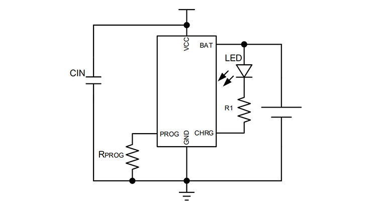
3. Typical Application Circuit Diagram
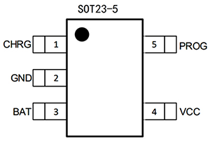
4. Pin Diagram and Functional Description
|
|
Pin Name | Pin Number | Functional Description |
| CHRG | 1 | Open-drain output for charging status indication | |
| GND | 2 | Ground | |
| BAT | 3 | Charging Current Output pin | |
| VCC | 4 | Power Input pin | |
| PROG | 5 | Constant current charging current setting and monitoring termina |
5. Features
- Normal Charging Cycle.
- Charging Current Setting.
- Termination of Charging.
- Charging Status Indicator.
- Thermal Limiting.
- Under-Voltage Lockout (UVLO).
- Automatic Recharging.
- Stability Considerations.
- Power Consumption Considerations.