

1. Specifications
(VIN=5V; TJ=25℃, unless otherwise specified)
| Symbol | Parameter | Condition | Min. | Typ. | Max. | Unit |
| VCC | Input Power Voltage | 4.25 | 6 | V | ||
| ICC | Input Power Current | Charging Mode (3), RPROG=10K | 110 | 500 | µA | |
| Standby Mode (Charge Terminated) | 40 | 80 | ||||
| Shutdown Mode (RPROG not connected, VCC﹤VBAT, VCC﹤VUV) | 30 | 60 | ||||
| VFLOAT | Adjustable Output (Float Charge) Voltage (Non-adjustable) | IBAT=30 mA, ICHRG=5 mA | 4.158 | 4.2 | 4.242 | V |
| IBAT | BAT Pin Current | RPROG = 10k, Current Mode | 90 | 100 | 120 | mA |
| RPROG = 2k, Current Mode | 450 | 500 | 550 | |||
| VBAT=4.2V, Standby Mode | 0 | 2.5 | 5 | µA | ||
| Shutdown Mode, RPROG not connected and VCC=0) | 0 | 2 | ||||
| Sleep Mode, VCC=0V | 0 | 2 | ||||
| ITRIKL | Trickle Charging Current | VBAT﹤VTRIKL,RPROG = 10k | 10 | mA | ||
| VTRIKL | Trickle Charging Threshold Voltage | RPROG = 10k,VBAT Rising | 2.8 | 2.9 | 3 | V |
| VUV | VCC Under-voltage Lockout Threshold | From VCC Low to High | 3.5 | 3.7 | 3.9 | V |
| VUVHYS | VCC Under-voltage Lockout Hysteresis | From VCC High to Low | 3.4 | 3.6 | 3.8 | mV |
| VMSD | Manual Shutdown Threshold Voltage | PROG Pin Up | 1.1 | V | ||
| PROG Pin Down | 0.9 | |||||
| VASD | VCC-VBAT Threshold Voltage | From VCC Low to High | 100 | mV | ||
| From VCC High to Low | 30 | |||||
| ITERM | C/10 Terminated Current Threshold | RPROG = 10k (4) | 10 | mA | ||
| RPROG = 2k | 50 | |||||
| VPROG | PROG Pin Voltage | RPROG = 10k, Current Mode | 0.9 | 1.03 | 1.1 | V |
| VCHRG | CHRG Pin Output Low Voltage | ICHRG = 5mA | 0.2 | 0.4 | V | |
| ΔVRECHRG | Battery Threshold Voltage | VFLOAT – VRECHRG | 100 | mV | ||
| TLIM | Thermal Protection Temperature | 120 | ℃ | |||
| tSS | Soft Start Time | IBAT = 0 to 1000V/RPROG | 100 | µs | ||
| tRECHRGE | Recharge Comparator Filter Time | VBAT High to Low | 2 | ms | ||
| tTERM | Terminate Comparator Filter Time | IBAT Falling Below ICHG/10 | 2 | ms | ||
| IPROG | PROG Pin Pull-up Current | 2 | µA |
Note: Exceeding the maximum operational range may damage the chip.
2. Product Features
- Programmable charging current up to 500mA.
- No external MOSFETs, sense resistors, or reverse diodes required.
- Constant current/constant voltage operation with thermal protection.
- Lithium battery charging via USB port.
- Preset charging voltage with 1% accuracy.
- Standby mode current of 40µA.
- 9V trickle charge voltage.
- Soft start limits inrush current.
- SOT23-5 package.
3. Typical Application Circuit Diagram
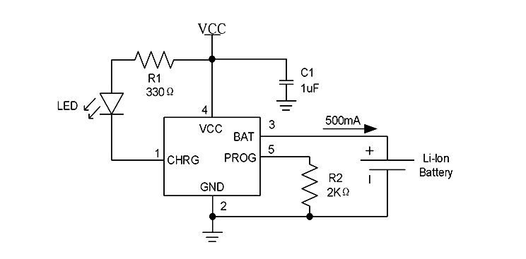
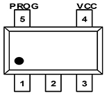
4. Pin Diagram and Functional Description
|
|
Pin Name | Pin Number | Functional Description |
| CHRG | 1 | Charging indicator pin | |
| GND | 2 | Ground | |
| BAT | 3 | Charging Current Output pin | |
| VCC | 4 | Power Input pin | |
| PROG | 5 | Charging current setting pin |