
1. Specifications
Unless otherwise specified, all parameters are measured at room temperature and referenced to the GND pin as the zero potential
| Symbol | Features | Condition | Unit | Min. | Typ. | Max. |
| System Parameters | ||||||
| VIN | Input Voltage Range | V | 4.5 | 5 | 5.8 | |
| Vbat | Battery Voltage | V | 2.8 | 4.35 | ||
| Charging Parameters | ||||||
| VIN Power Loss Monitoring | VIN from low to high | Vin>BAT | mV | 100 | ||
| VIN from high to low | Vin>BAT | mV | 30 | |||
| Vfloat | Float Threshold Voltage | VIN=5.0V | V | 4.152 | 4.20 | 4.242 |
| Ichg | Charging Current | VIN=4.75-5.25V
Prog=gnd |
A | 1.00 | ||
| VTRKL | Trickle to Constant Current Transition | VBAT from low to high | V | 2.8 | ||
| VTRHYS | Trickle Charge Hysteresis Voltage | mV | 100 | |||
| VRECHG | Recharging Threshold Voltage | V | 4.1 | |||
| Discharge Parameters | ||||||
| Vo | Boost System Output Voltage | V | 4.95 | 5.10 | 5.25 | |
| Iout | Output Current | BAT=3.6V Vout>4.8V |
A | 0.9 | 1.0 | 1.20 |
| VOVP | Output Overvoltage Protection | BAT=3.6V | V | 5.8 | ||
| VOVP_DIS | V | 5.4 | ||||
| VUVLO | Boost Undervoltage Protection | BAT from high to low | V | 2.8 | ||
| VUVLO_R | Boost Undervoltage Recovery | BAT from low to high | V | 3.20 | ||
| IBAT1 | Vout=5.5V,No switching | mA | 0.2 | |||
| IBAT2 | Vout=4.5V,switching | mA | 1 | |||
| FOSC | Operating Frequency | MHz | 1 | |||
| Iauto_off | Automatic Shutdown Load Current | BAT=3.6V Cout=22uF |
mA | 50 | ||
| Istb | Standby Current | BAT=3.6V | uA | 15 | 40 | |
| OTP | Overtemperature Protection | degC | 150 | |||
| OTP_HYS | Hysteresis | degC | 30 | |||
2. Product Features
- Charging and discharging can share a single port, intelligently identifying charging input and load output.
- Integrated maximum 1A linear charging mode with externally adjustable charging current.
- Three-stage charging (trickle/constant current/constant voltage) with a constant voltage of 4.20V (typical), supporting charging of 0V batteries.
- The built-in charging function automatically reduces the charging current based on temperature rise, starting to decrease at 130°C and can go down to 0.
- The charging input has anti-backflow protection, eliminating the need for a backflow prevention diode.
- The boost circuit uses synchronous rectification, achieving a maximum efficiency of 91% with low heat. generation, providing a fixed output of 5.10V (typical value) without requiring external resistors.
- Boost output current of 1.0A (BTP=3.6V) with constant power output functionality, including comprehensive overcurrent and short-circuit protection, built-in temperature protection, and automatic boost shutdown in case of overheating.
- The boost automatically activates upon load insertion and goes into sleep mode when the load is removed.
- Low battery voltage warning function.
- Supports single or dual LED indicators for charging and discharging.
- 4KV ESD protection.
- Fixed switching frequency of 1MHz.
- Battery overcharge and over-discharge protection.
- SOP8 Compact Package.
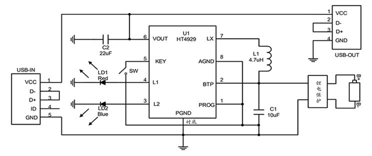
3. Typical Application Circuit Diagram
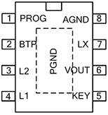
 4. Pin Diagram and Functional Description
|
|
Pin Name | Pin Number | Functional Description |
| PROG | 1 | Charge Current Setting (GND 1A) | |
| BTP | 2 | Battery Pin | |
| L2 | 3 | Indicator Light 2 | |
| L1 | 4 | Indicator Light 1 | |
| KEY | 5 | Button | |
| VOUT | 6 | Output Voltage Pin | |
| LX | 7 | Inductive Pin | |
| AGND | 8 | Analog Ground |
5. Features
- Charging Management Module.
- Boost Converter Module.
- Automatic Switch Module for Simultaneous Charging and Discharging.
- Charge/Discharge Indicator Lights.
- Charger Detection During Single-Port Discharge.
- PCB Layout Reference.
- Electrostatic Protection Measures.