1. Specifications
Unless otherwise specified, all parameters are measured at room temperature and referenced to the GND pin as the zero potential
| Symbol | Features | Condition | Unit | Min. | Typ. | Max. |
| System Parameters | ||||||
| VIN | Input Voltage Range | V | 4.5 | 5 | 5.5 | |
| Vbat | Battery Voltage | V | 2.95 | 4.4 | ||
| Charging Parameters | ||||||
| VIN Power Loss Monitoring | VIN from low to high | Vin>BAT | mV | 250 | ||
| VIN from high to low | Vin>BAT | mV | 50 | |||
| Vfloat | Float Threshold Voltage | V | 4.158 | 4.22 | 4.242 | |
| Ichg | Charging Current | VIN=4.75-5.25V | A | 0.7 | ||
| VTRKL | Trickle to Constant Current Transition | VBAT from low to high | V | 2.8 | ||
| VTRHYS | Trickle Charge Hysteresis Voltage | mV | 100 | |||
| VRECHG | Recharging Threshold Voltage | V | 4.1 | |||
| Discharge Parameters | ||||||
| Vo | Boost System Output Voltage | V | 4.95 | 5.1 | 5.25 | |
| Iout | Output Current | BAT=3.6V Vout>4.8V |
A | 0.7 | ||
| VOVP | Output Overvoltage Protection | V | 5.8 | |||
| VOVP_DIS | Output Overvoltage Protection Recovery | V | 5.6 | |||
| VUVLO | Boost Undervoltage Protection | BAT from high to low | V | 2.95 | ||
| VUVLO_R | Boost Undervoltage Recovery | BAT from low to high | V | 3.20 | ||
| IBAT1 | Vout=5.5V,No switching | mA | 0.5 | |||
| IBAT2 | Vout=4.5V,switching | mA | 1.5 | |||
| Iauto_off | Automatic Shutdown Load Current | BAT=3.6V Cout=22uF |
mA | 80 | ||
| Iq | Static Current | BAT=3.6V | uA | 10 | 30 | |
| FOSC | Operating Frequency | MHz | 1 | |||
| OTP | Overtemperature Protection | degC | 150 | |||
| OTP_HYS | Hysteresis | degC | 20 | |||
2. Product Features
- Highly integrated with minimal external components.
- Built-in linear charging mode with a typical current of 7A.
- Three-stage charging (trickle/constant current/constant voltage) with a constant voltage of 4.20V (typical), supporting charging of 0V batteries.
- The charging current automatically decreases based on temperature rise, starting from 130°C, and can drop to zero.
- The charging input has anti-backflow protection, eliminating the need for a backflow prevention diode.
- The boost converter uses synchronous rectification with an efficiency of up to 91%, generating low heat, providing a fixed output of 5.1V (typical) without requiring external resistors.
- Output current of 7A (typical at battery voltage of 3.6V), featuring constant power output with complete overcurrent and short-circuit protection.
- Automatic boost activation upon load insertion and automatic sleep mode when the load is removed.
- Low battery voltage warning function.
- Supports single or dual LED indicators for charging and discharging: LED1 blinks during charging and lights up when fully charged; it lights up during discharge, blinks when battery voltage drops below 3.2V (typical), and turns off when it falls to 2.95V due to undervoltage shutdown.
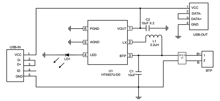
3. Typical Application Circuit Diagram
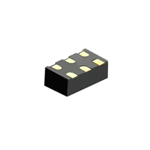
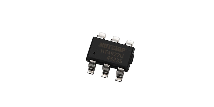
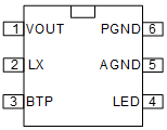
4. Pin Diagram and Functional Description
| Pin Name | Pin Number | Functional Description | |
| VOUT | 1 | Output Voltage Pin | |
| LX | 2 | Inductive Pin | |
| BTP | 3 | Battery Pin | |
| LED | 4 | Indicator Light | |
| AGND | 5 | Analog Ground | |
| PGND | 6 | Power Ground |
5. Features
- Charging Management Module.
- Boost Converter Module.
- Automatic Switch Module for Simultaneous Charging and Discharging.
- Charge/Discharge Indicator Lights.
- Charger Detection During Single-Port Discharge.
- PCB Layout Reference.
- Electrostatic Protection Measures.
