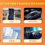
In the field of portable electronic device design, power management—specifically lithium battery charging management—remains a critical concern for engineers. A reliable, highly integrated charging IC that seamlessly collaborates with modern digital control systems often determines the final stability of a product and the efficiency of its development process.
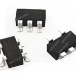
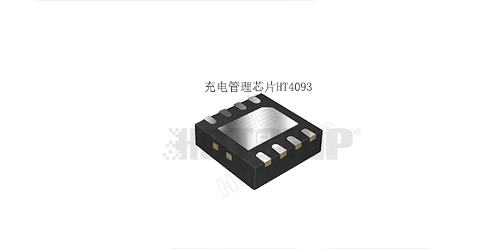
This article provides an in-depth analysis of the HT4093 from Shenzhen Hotchip Technology Co., Ltd. This is a single-cell linear lithium battery charger capable of withstanding up to 40V at its input and delivering a programmable charging current of up to 1.2A. More than just a charging IC, the HT4093 is an intelligent charging solution deeply optimized for MCU-based environments.
I. Core Parameters and Positioning: Built for Demanding Industrial and Consumer Applications
The design intent of the HT4093 is clear: to simplify external circuitry while maximizing flexibility for intelligent control, all without compromising safety. Its core specifications determine its broad applicability:
40V Input Withstand Voltage: This is the most prominent technical feature of the HT4093. In today’s environments with USB-C adapters and fluctuating industrial or automotive power supplies, a 40V tolerance provides a substantial safety margin, effectively preventing damage from input surges or incorrect plug insertion, significantly reducing field failure rates.
1.2A Programmable Charging Current: This covers typical applications ranging from small-capacity batteries in TWS earbuds to medium-capacity batteries in portable speakers, atomizers, and more. The charging current is easily set using an external resistor, offering flexible design.
Optimized for MCU Collaboration: This is the core feature that distinguishes the HT4093 from conventional general-purpose linear chargers. Its logic level design, enable logic, and control methods are all tailored for seamless communication with 3.3V or 5V logic MCUs.
II. In-Depth Technical Analysis: Perfect Fusion of Three-Stage Charging and Intelligent Collaboration
To understand the value of the HT4093, one must look beyond the parameters and see how it combines classic charging theory with modern digital control requirements.
1. Classic Charging Strategy with Superior Thermal Management
The HT4093 adopts the standard lithium-ion three-stage charging mode: Trickle/Constant Current/Constant Voltage.
Pre-charge (Trickle): When the battery voltage is below the threshold (approx. 2.9V), the chip charges at 10% of the set constant current, safely activating deeply discharged cells.
Constant Current Charge: Once the battery voltage exceeds the pre-charge threshold, the current rises to the set 1.2A maximum for fast charging.
Constant Voltage Charge: When the battery voltage reaches the 4.2V regulation voltage, the charger enters constant voltage mode. The current naturally decays and terminates automatically when it falls to 1/10th of the constant current value, completing the cycle.
Thermal Regulation Mechanism: During linear charging, high input voltage and high current can cause the chip to heat up. The HT4093’s built-in thermal regulation loop monitors the junction temperature in real-time. If it gets too high, the loop intelligently reduces the charging current to prevent overheating, ensuring safe and continuous charging even in adverse conditions. This allows engineers to be less concerned about heat dissipation design, simplifying PCB layout.
2. Designed “Communication Language” for MCUs
The HT4093 features carefully considered signal interactions, making it exceptionally suitable for smart devices.
Level Matching: The voltage levels on its status pins are clamped to a voltage no higher than the battery voltage. This means that when the battery is low, the voltage on these pins connecting to the MCU is also low, preventing any I/O port stress or leakage current due to level mismatch—a highly practical detail.
Active Low Enable: The chip’s CE (Chip Enable) pin is designed to be Active Low and has a built-in pull-down resistor. This corresponds directly to the fact that MCU I/O pins are often high-impedance or high-level during power-on reset. Using an active low enable ensures the charger stays off until the MCU initializes and actively pulls the CE pin low, achieving a “default off, actively turned on” safety logic. It also perfectly supports 0V battery activation.
Control Flexibility: The MCU can not only dynamically adjust the charging current via the PROG pin but also halt charging mid-cycle by controlling the CE pin. Furthermore, it can manually initiate recharging at any battery voltage through a specific sequence, breaking the limitation of traditional chargers that must wait for the battery voltage to naturally fall to a recharge threshold. This enables applications requiring forced full-charge states.
III. Application Scenarios and Advantages: Reliability is a Common Need—From Desk Lamps to Atomizers
Based on the above features, the HT4093 is widely applicable to various portable devices. Let’s analyze two typical scenarios to see how it solves real-world problems.
Scenario 1: High-End Dimmable Desk Lamps
Modern desk lamps are more than just lighting tools; they integrate dimming, timers, color temperature adjustment, and even wireless charging, often relying on an MCU as the control core.
Pain Points: Many desk lamps use 12V or even 24V power adapters—relatively high voltages. Traditional low-voltage charging ICs would require additional step-down circuits, increasing cost and complexity. Simultaneously, charging status needs to be reported back to the MCU for display on indicators or screens.
HT4093 Solution Advantages:
1. Direct Power Supply: With 40V input tolerance, the HT4093 can directly draw power from a 24V adapter for charging management, eliminating complex front-end step-down circuitry and simplifying power design.
2. Smart Interaction: The MCU can read the STATC/STATD pins (dual outputs for charging status) to accurately know states like “charging,” “charge complete,” or “battery fault,” displaying them on a screen. The MCU can also pull the CE pin high during “silent mode” (e.g., at night) to suspend charging and eliminate potential noise.
3. Safety: Features like battery reverse protection and temperature monitoring add extra safety layers to the overall product.
Scenario 2: Smart Atomizers
Atomizers (e.g., e-cigarettes, medical nebulizers) have extremely stringent requirements for PCB space and power consumption.
Pain Points: Very limited space, heat concentration, and need to collaborate with the MCU for battery level display and various protections.
HT4093 Solution Advantages:
1. High Integration: The internal PMOSFET architecture eliminates the need for an external isolation diode. The tiny DFN3×3-8 package and minimal external components save valuable PCB area.
2. Low Standby Current: When the device is in standby, the MCU can put the HT4093 into shutdown mode, reducing supply current to below 100µA, thus significantly extending overall battery life. When input power is removed, the current drawn from the BAT pin drops below 1µA, barely consuming any battery energy.
3. 0V Charging Support: The active low enable design allows the MCU to initiate charging at any time, even when the battery is completely depleted to 0V, ensuring the device can be reliably awakened and charged after deep discharge.
IV. Reliability Design: More than Just Charging—A Protective Barrier
In product design, reliability is the ‘1’, while performance follows as the ‘0’s. The HT4093 provides a multi-layered protective barrier:
1. Input Over-Voltage Protection (OVP): When the input voltage exceeds 6.7V (typical), the chip quickly shuts down the charging path to protect the downstream circuits and the battery. Combined with the 40V absolute maximum rating, this provides dual protection: withstand voltage and active cutoff.
2. Battery Reverse Connection Protection: If the battery is connected backwards, the chip immediately enters a protection state, preventing high current from damaging the battery or the chip. Its BAT pin tolerates brief voltage exposure from -4.2V to 12V, showcasing robust reliability.
3. Soft-Start: Upon power-up or battery connection, the soft-start circuit limits inrush current, preventing stress on the power source and connectors.
4. Battery Temperature Monitoring: By connecting an NTC thermistor to the TEMP pin, the chip monitors battery temperature in real-time, charging only when within safe temperature limits—essential for high-safety applications.
V. A “Thinking” Charging Core for Smart Hardware
Looking at all the features of the HT4093, it is clear that this is not just a “charge and forget” simple device. The design team at Hotchip clearly understands the modern smart hardware industry’s extreme demand for collaboration, control, and safety.
It retains the simplicity and cost-effectiveness inherent to linear charging ICs, yet through thoughtful designs like level clamping, active-low enable, and programmable control, it offers engineers immense design freedom. This makes the HT4093 not just a power management IC, but an intelligent execution unit that understands MCU commands, reports accurate status, and proactively responds to various fault conditions.For engineers designing smart lighting, portable medical devices, industrial handheld terminals, or various IoT devices, the HT4093 offers an ideal choice that balances performance, safety, and design flexibility. Its 40V tolerance sets a safety boundary for the system, its 1.2A current ensures charging efficiency, and its MCU-friendly interfaces open new possibilities for intelligent power system design.