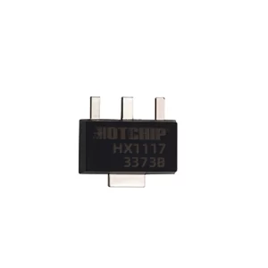
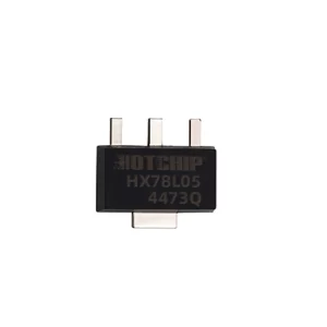
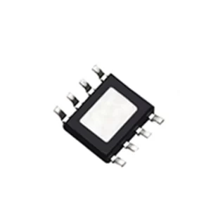
1. Specifications
| Symbol | Features | Condition | Unit | Min. | Typ. | Max. |
| System Parameter | ||||||
| VIN | Input Voltage Range | V | 4 | 5 | 7 | |
| VIN Power-down Monitoring | from Low to High | Vin>BAT | mV | - | 100 | - |
| from High to Low | - | 30 | - | |||
| Vfloat | Float Charging Threshold Voltage | VDD = 5V, R2 not connected. | V | 4.18 | 4.22 | 4.26 |
| Ibat | BAT Backflow Current | Vcc=3.5V,Vbat=4.2V | uA | - | ±0.5 | ±5 |
| Vcc=0V, R2 not connected | — | — | 1 | |||
| VTRKL | Trickle to Constant Current Transition | VBAT from Low to High | V | - | 2.8 | - |
| VTRHYS | Trickle Charging Hysteresis Voltage | mV | - | 100 | - | |
| VUV | Vcc Undervoltage Lockout Threshold | Vcc from Low to High | V | - | 3.7 | - |
| VUVHYS | Vcc Undervoltage Blocking Hysteresis | mV | - | 200 | - | |
| Vmsd | Manual Shutdown Threshold Voltage | V | - | 1.2 | - | |
| VmsdHYS | Manual Shutdown Hysteresis Voltage | mV | - | 50 | - | |
| Vprog1 | PROG Voltage at Trickle | V | - | 0.1 | - | |
| Vprog2 | PROG Voltage at High Current | V | - | 1 | - | |
| OTR | Over-temperature Recovery (Constant Temperature Mode) | VDD=5V | ℃ | - | 130 | - |
2. Product Features
- Preset 22V ±1% charging voltage.
- Externally adjustable charging voltage, with a maximum approaching the input voltage.
- Three-stage charging: trickle, constant current, and constant voltage; externally adjustable charging current, with a maximum charging current of 1A.
- Maximum input voltage: 7V.
- Supports charging 0V batteries.
- Standby current less than 1μA.
- Short-circuit protection.
- BAT-VDD reverse current protection.
- Battery reverse polarity protection to prevent chip damage from incorrect battery connection.
- Intelligent temperature control, reducing charging current as temperature rises to prevent overheating while delivering maximum charging current.
- Soft-start limits inrush current.
- Can directly charge single-cell lithium-ion batteries from a USB port.
- Automatic recharge.
- Supports single-light and dual-light modes.
- Highly integrated with minimal external components.
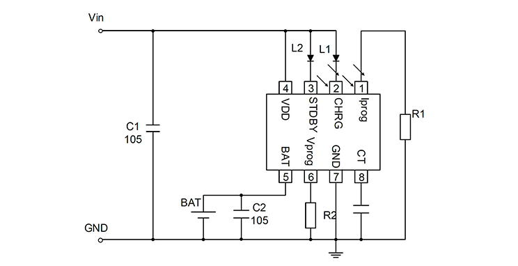
3. Typical Application Circuit Diagram
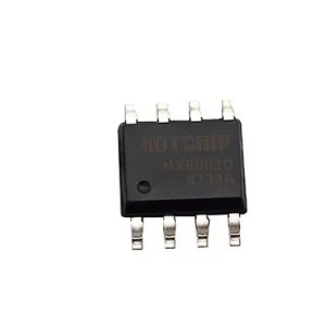
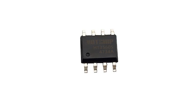
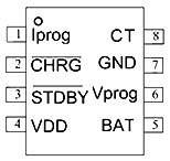
4. Pin Diagram and Functional Description
| Pin Name | Pin Number | Functional Description | |
| Iprog | 1 | Charging Current Adjustment pin | |
| CHRG | 2 | Charging Indicator pin | |
| STDBY | 3 | Saturation Indicator pin | |
| VDD | 4 | Power Supply Positive pin | |
| BAT | 5 | Battery Positive pin | |
| Vprog | 6 | No-load Voltage Adjustment pin: 1. When R2 is not connected, Vfloat = 4.22V.
2. By adjusting the resistance value of R2, the float charge threshold voltage can be set according to usage requirements. |
|
| GND | 7 | Power Supply Negative pin (Ground) | |
| CT | 8 | Charge Completion Delay Setting pin |
5. Features
- Normal Charging Cycle.
- Charging Current Setting.
- Shutdown Delay Setting.
- Battery Reverse Polarity Protection Function.
- Charging Status Indicator (CHRG STDBY).
- Thermal Limiting.
- Under-Voltage Lockout (UVLO).
